
POST-RESIDENCE, L.A: 2070
SANTA MONICA, LOS ANGELES, CA, USA
STUDIO: ARCH 8020, Prof. Matthew Jull, University of Virginia, Spring 2019
PROGRAM: To speculate on the future of domesticity, and the potential for new, collective forms of dwelling for a currently under-utilized site in Santa Monica adjacent to the terminus of the Metro’s Exposition line. The project begins with the articulation of a future scenario for the year 2070 at an urban and site scale, and culminates with the development and resolution of a detailed architectural strategy, which includes material, structural, mechanical, and environmental systems.


What might Los Angeles’s endless fabric of houses and urban homesteads, constructed upon the great promise of infinite land, limitless ecological bounty, and the hubris of the automobile, look like without its infrastructural straight-jackets?
In a near-future Los Angeles, where autonomous ride-share fleets have replaced private vehicles, online commerce has supplanted physical shopping, digital augmentation of humanity’s physical and cognitive capabilities is fully normalized and invisible, and real-time drone delivery and removal of goods has rendered personal property and storage obsolete, housing could cease to be a discrete building typology. It would no longer be spatially and organizationally governed by the needs of the automobile, the nuclear family, the storage of private property, or legal and administrative boundaries, but instead around a broad vision of fluid urban community. Future housing could therefore be lighter, thinner, simpler, and more dynamic than its static, thick-footprinted predecessors; not to mention more customizable, expandable, open to the outdoors, and less reliant on mechanical systems. Moreover, housing would cease to be beholden to the spatial logics of anachronistic infrastructures: deeds and plats, rights of way, medians, crosswalks, sidewalks, and all manner of engineered buffer spaces.
THE CITY, 2070:


1. Real-time delivery and removal of goods via drone will be the norm, eliminating the need for domestic storage space, and making the owning of things like furniture obsolete.
2. Cloud-synced autonomous ride-share fleets will replace the conventional automobile, eliminating the need for most current vehicular infrastructure such as sidewalks and medians.
3. Physical and digital infrastructures at both the urban, and human scales will become increasingly thin, discrete, or invisible, and no longer a spatial determinator of urban form.
4. The obsolescence of many industries renders the conventional notion of “work” an anachronism. Instead, life in the city is defined not by tasks and functions, but by collective and private experiences.
THE NEIGHBORHOOD, 2070:


1. The “perimeter” of the site as a legal and infrastructural framework has become irrelevant. “Subdivision” is likewise not applicable. The Spatial logic of the new fabric is instead the expandable 25 foot by 25 foot square grid.
2. The only infrastructure remaining with a relevant spatial figure on the site is the light rail line, which has been extended to continue on down the coast, and has been re-routed across the site so as to point due south, a 32 degrees offset from the square grid.
3. All primary site circulation is to be parallel or perpendicular to the North-South meridian established by the 32 degree offset. Smaller cross connections are to follow the square grid.
4. A group of 12 grid bays (4 wide, and 3 tall) make up one site “tile” Within a tile, three grid bays (by area) are to be enclosed space, and the remaining area is to be outdoor space.

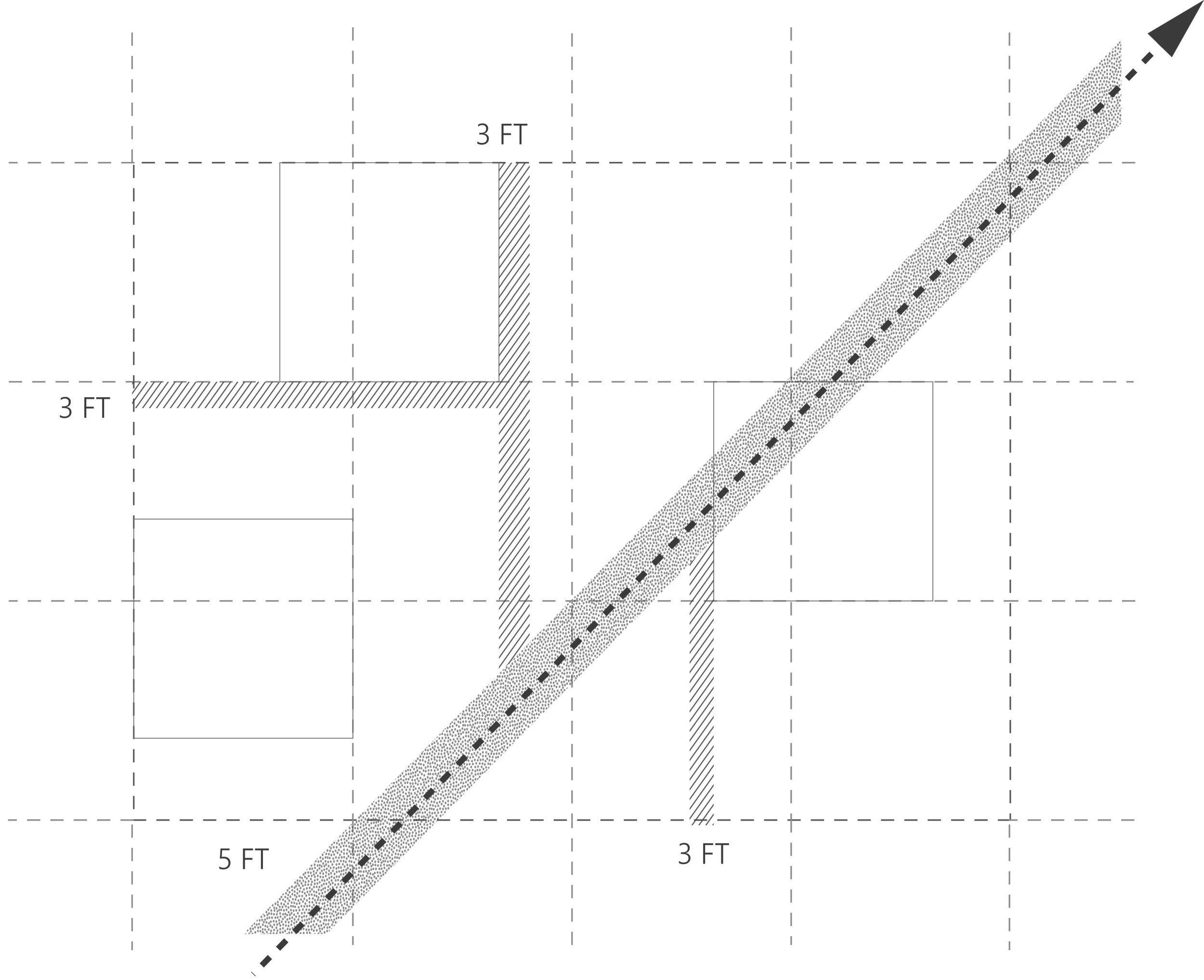


5. To generate visual interest, allow for sight-lines and variety, and promote porosity, each enclosed mass will be offset by 10 feet from a grid line in a minimum of one axial direction. These masses may not move obliquely.
6. Primary site paths are to be 5 feet wide, and made of pavers. Secondary paths are to be 3 feet wide and unpaved. All other built elements, including landscape constructions, must have dimensions which are factors of 25.
7. When the tiles aggregate, they do so in rows, and each row is allowed to offset an increment of 5 feet from the adjacent row. A row cannot offset the same distance and in the same direction as its adjacent rows.
8. Tiles can aggregate infinitely in any direction, creating a cellular block-type fabric independent of the former street grid. Within this framework, each tile can organize itself uniquely and independently.
SITE PLAN: SANTA MONICA, 2070


THE ARCHITECTURE, 2070:


1. The three masses within each tile must relate to one another as a single, cohesive unit, whilst also existing as a porous part of a larger network.
2. Considering that there are an infinite number of possible permutations, no two masses shall be exactly identical.
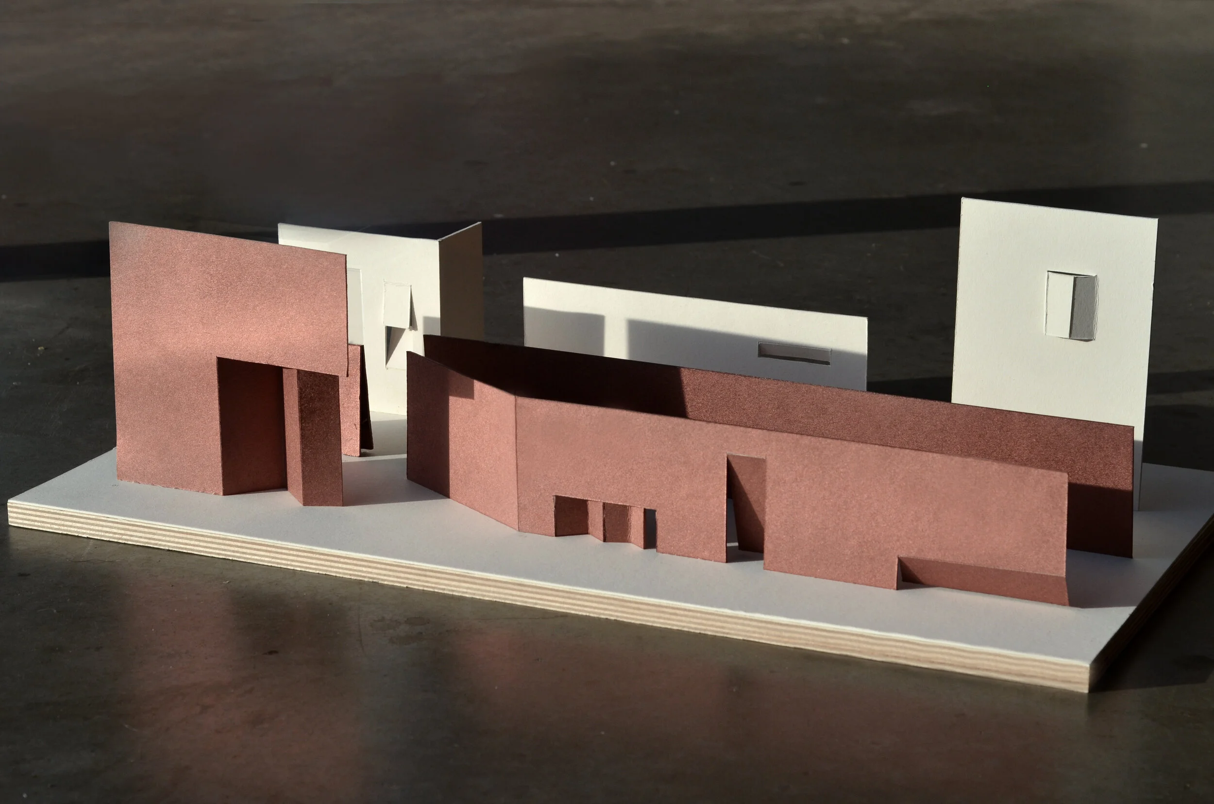
3. Each building mass is to have a rectangular envelope, and is to be exactly 30’ tall, measured from the lowest point of local grade to top of parapet. Each mass will be white and monolithic in finish, exterior and interior.


4. All building masses are to be naturally ventilated, and primarily plein-air, yet the overall massing must read as one volume. All apertures must be in some way operable. No HVAC is required, but plumbing is needed.
5. All masses will be open and accessible to the collective public at the ground floor.
6. All masses will provide some accommodation for sleeping and washing above the ground floor.
MODULE DESIGN
Post-residence, LA: 2070 imagines that the act of dwelling—so central to the cultural fabric of the current city—will not be relegated to the formal contrivance of the “residence” or “home.” Accordingly, a firm boundary between domestic life and public life will cease to exist: the city is meant for living, and in 2070, one may live freely anywhere within it. Here, the ground plane has been re-defined as the uninterrupted zone of the public: a field condition punctuated by a rhythm of collective and experientially programmed spaces. The last vestiges of private domesticity, sleeping and washing, are now distributed freely above these programs in temporally occupiable, loft configurations. While there is potential for an infinite number of interior permutations, thirty-six schematic module concepts are illustrated above, and three hybridized concepts are expanded upon in architectural detail below. The three developed modules comprise one site tile, and each module is spatially and programmatically focused around one experiential condition. Module A aims to cultivate an experience of solace and individual contemplation, module B promotes relaxation and recreation, and module C encourages communal gathering and social interaction. Paths, groundcover, plantings, and other landscape elements, which link the three modules, create spatial coherence within tiles, and connect modules to others in neighboring tiles, can vary across the site to adapt and reflect subtle variations in topography and geology.
SITE AND MODULE FLOORPLANS
SECTION A
SECTION B
SECTION C


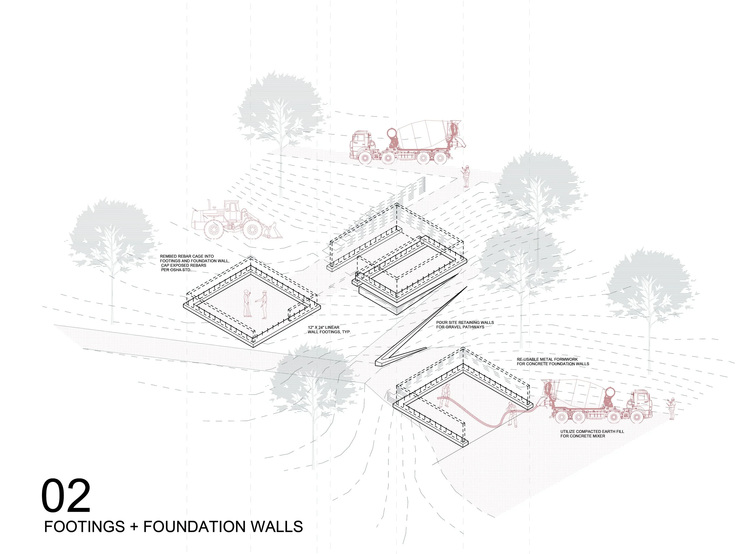
PHASING + ASSEMBLY


“THIN-NESS” AND “LIGHT-NESS” AS MATERIAL + TECTONIC STRATEGY
The project’s aspiration toward a barrier-free, fluid urbanity is reflected at the architectural scale through a material, programmatic, aesthetic, and tectonic pursuit of “thin-ness” and “light-ness.” All modules are constructed with low-cost, lightweight, and easily assembled components which not only minimize the material thickness of building elements and the physical separation between interior spaces and the outdoors, but also decrease the complexity of layered building assemblies, reduce embodied material energy, and eliminate the need for most storage, furniture, and redundant mechanical systems. Walls and floors are constructed with modular fiberglass reinforced polymer panels, with additional spanning structure provided by small W, C, L, and T profile extrusions of the same material. Additionally, braided steel tension cables span through the open cavities of the panels, creating a multi-directional network of flexible, lateral support for seismic resistance. The edge profiles of building elements and apertures are furthermore tapered to create the appearance of near flatness, and connections are detailed to enhance the somatic and visual effect of thinness and lightness through cantilevers, tapered edges, floating planes, visual reveals, and suspended masses.


CABLE SCREEN SECTION
REFLECTING POOL REVEAL / BENCH
1. Fiberglass Reinforced Polymer Structural Panel System, white finish. 2. Internal horizontal reinforcing braided steel or polymer tension cables. 3. C6 Steel or Fiberglass Reinforced Polymer Structural Channel. 4. L3x3 Steel or Fiberglass Reinforced Polymer Angle. 5. Exterior screen element, braided steel or polymer cables. 6. Metal spacers, weld or bolt to primary structure. 7. White fiberglass ext. cladding, mount to galv. metal furring channels. 8. Double-pane, Low-E coated, fixed tempered glass skylight, Aluminum hardware, thermally broken, white kynar finish. 9. Light gauge, cold-rolled steel furring channels.
10. Steel J-bracket and rolling wheel at mani-folding cable screen. 11. Tapered corner at min. 60 degree return. 12. Double-pane, Low-E coated, tempered glass awning window, Aluminum hardware, thermally broken, white kynar finish. 13. Louvered vent register to facilitate passive air exchange. 14. Internal vertical reinforcing braided steel or polymer tension cables. 15. Utility cavity for plumbing. 16. Steel embedded bearing plate and anchor rods. 17. Exterior drain channel, C4 Steel structural channel, typical. 18. Exterior termination strip and flashing. 19. Overflow drain channel, steel structural channel, varying thickness.
20. Cold water pool, blackened steel plate lined, weld at seams. 21. Structural concrete foundation wall. 22. Structural concrete foundation footing, 12” x 24,” typical. 23. Structural concrete slab on grade. 24. Sub-slab rigid insulation board. 25. Foundation waterproofing, fluid applied. 26. Crushed stone and 4” perforated drain pipe. 27. Reflecting pool, blackened steel plate edge set into concrete. 28. Mount glazing mullion outboard to L1.5x1.5 structural steel angle. 29. Double-pane, Low-E coated, tempered direct set glazing, Aluminum hardware, thermally broken, white kynar finish.
30. Slate floor pavers to match exterior pathways. 31. Bent steel plate bench, taper fascia to hide window mounting. 32. Viscoelastic polyurethane “memory” foam at sleeping lofts 33. Bent steel plate, varying thickness. 34. HSS 6x3 Structural steel hollow tube, marine grade coating, black. 35. 3/4” blackened steel structural floor plate. 36. 1/2” clear frosted acrylic partition and bottom rail mount. 37. Embed steel channel into concrete slab for cable screen wheel track. 38. Drain pan under raised floor at bathroom, slope to drain. 39. Raised bathroom floor panel, radiant heated via copper pipes.